Para aquellos de ustedes que poseen grupos electrógenos diésel, El mantenimiento de los grupos electrógenos es crucial. Mi documento tiene como objetivo proporcionar una introducción detallada a los Mantenimiento de Grupos Electrógenos Diesel durante la operación, sistemas de enfriamiento, gases de acoplamiento, Generadores, y paneles de control
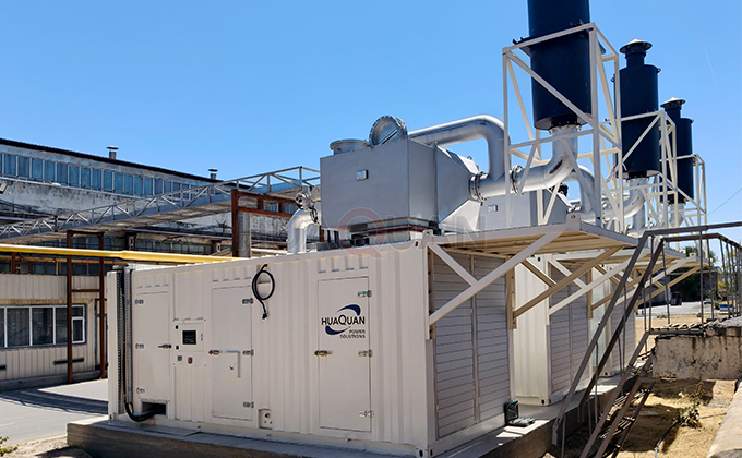 Generador de gas Antecedentes del proyecto de recuperación de calor residual de centrales eléctricas" ancho ="680" altura ="420" />
(1) Mantenimiento del grupo electrógeno diésel durante el funcionamiento.
Después de que el grupo electrógeno diesel genere electricidad normalmente, debes monitorear el motor diesel, generador, Panel de control, etc.. y mantener registros periódicos de sus condiciones de funcionamiento.. Preste atención a los cambios de voltaje., frecuencia, fuerza, e instrumentos de monitoreo del motor en todo momento, y hacer ajustes razonables de manera oportuna.
Según los requisitos de los manuales de uso y mantenimiento de productos como motores., generadores, y paneles de control, Debe realizar trabajos de mantenimiento durante el funcionamiento y conservar registros para referencia futura..
Razones y soluciones para el disparo accidental del interruptor principal del generador:
1) Si hay un punto de cortocircuito en el circuito de carga del generador y falla la protección de rama, provocando un viaje, Debes identificar el punto de cortocircuito y eliminarlo.;
2) Debido al ambiente húmedo o mantenimiento inadecuado, El agua interna del generador puede humedecerse y la resistencia del aislamiento puede disminuir., provocando un cortocircuito y disparando el interruptor principal. Debe utilizar un megaóhmetro para comprobar el valor de la resistencia de aislamiento.. Si es inferior a 2M Ω, El generador debe secarse para que la resistencia de aislamiento cumpla con los requisitos antes de su uso.. Para evitar que el interruptor principal se dispare debido al cortocircuito interno del generador., Debe utilizar un megaóhmetro para comprobar la resistencia del aislamiento cuando la unidad se enciende o se estaciona durante un período de tiempo.. Después de cumplir con los requisitos, puedes iniciar la máquina nuevamente;
3) Si el interruptor principal se dispara debido a subtensión o pérdida de tensión del generador, Debes verificar la velocidad del generador y el circuito de excitación., identificar la causa del mal funcionamiento, solucionar el problema, y luego reinicie la máquina;
4) Si el interruptor principal se dispara debido a una sobrecarga del generador, debe eliminar parte de la carga para garantizar el suministro normal de energía al generador..
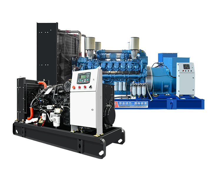
(2) Mantenimiento y conservación del sistema de refrigeración.
El sistema de refrigeración del motor debe someterse a diversos mantenimientos técnicos de acuerdo con los requisitos de uso y mantenimiento de cada componente del sistema.. Además, se deben tomar las siguientes precauciones:
1. Requisitos para la capacidad del agua de refrigeración y el tanque de expansión.
Para grupos electrógenos diésel, deberías instalar un tanque de expansión, que debe ser 500 mm más alto que el tubo de salida del motor. El diámetro del tubo de desbordamiento de escape debe estar entre 6 mm y 10 mm., y el diámetro del tubo suplementario de entrada debe ser ≥ 20 mm. El volumen del tanque de expansión no debe ser inferior a 150 litros..
2. Precauciones para todo el sistema de refrigeración durante el uso.
2.1 Controlar estrictamente la calidad del agua de refrigeración., y el agua de refrigeración utilizada para el motor debe cumplir con los requisitos especificados. Nunca debe agregar refrigerante a un motor sobrecalentado.. En cambio, primero deje que el motor se enfríe naturalmente.
Después de iniciar la unidad, Debes abrir las válvulas de liberación de aire del enfriador de aceite., intercooler, bomba de agua, y enfriador de acoplamiento para expulsar el gas en el sistema de enfriamiento.
Durante el funcionamiento de la unidad, Las temperaturas de entrada y salida del agua de refrigeración deben controlarse estrictamente. Debe asegurarse de que la temperatura del agua en circulación a alta temperatura esté dentro del rango de 75-85 ℃, La alta temperatura del agua de salida no debe exceder 90 ℃, y la temperatura del agua en circulación a baja temperatura no debe exceder 50 ℃.
Cuando la temperatura ambiente es inferior 5 ℃, Debe precalentar el agua de refrigeración antes de arrancar el grupo electrógeno diésel.. La temperatura del agua debe elevarse al menos 20 ℃ antes de comenzar.
Cuando la temperatura ambiente es inferior a cero grados, lo mejor es utilizar anticongelante. Si se utiliza agua de refrigeración normal, después de apagar la unidad, espere a que la temperatura del agua baje 40 ℃ y drene toda el agua de refrigeración en los sistemas de circulación de alta y baja temperatura., Prestando especial atención al drenaje del agua en las tuberías de cobre del enfriador de aceite y del enfriador del acoplamiento para evitar la congelación y el agrietamiento de los componentes..
2.6 Debe comprobar periódicamente el nivel del agua de refrigeración e instalar un indicador de nivel de agua en la cámara de agua del radiador.. Cuando el nivel de líquido indicado es bajo, you should immediately replenish the cooling water.Only when the unit is stopped and the water inlet cover is cooled to a point where it can be touched by hand, slowly unscrew the water inlet cover.
2.7 Regularly check the tension of the fan drive tape to maintain the efficiency of the fan operation.
2.8 Strictly follow the maintenance requirements of each component, regularly clean and remove scale to maintain good cooling effect.
When the diesel generator set is working, you must install protective covers on the fan and pulley to ensure personal safety.
2.10 In cold seasons, ordinary radiator louvers should be considered for use.To reduce heat loss.
3. Mantenimiento y conservación del sistema de ciclo cerrado de refrigeración.
3.1 Use and maintenance of radiator
The exposed surface of the radiator is easily covered by oil stains and sandstorms;If the water quality is not treated properly, its internal waterways are prone to erosion or scaling by cooling water.These factors directly affect the heat dissipation effect, so it is necessary to maintain a clean working environment and strictly use qualified coolant during use. Al mismo tiempo, regular maintenance and cleaning should be carried out. The methods are:
3.1.1 Use compressed air with a pressure of 588-764kPa to blow the surface of the radiator in the opposite direction of the fan airflow.
When the surface of the radiator is severely contaminated with oil or blocked by scale, aceite, or rust, it should be disassembled and cleaned. When cleaning the core assembly, it should be first cleaned with a brush in alkaline water, then rinsed multiple times with clean water, and finally dried with compressed air.
When individual cold flat pipes are blocked and cannot be unblocked or the pipes are broken and cannot be welded, the ends of the pipe can be blocked, but the number of blockages shall not exceed one percent of the total.
4. Mantenimiento y conservación del sistema de accionamiento del ventilador.
The elastic drive bracket of the fan is a direct drive mechanism, and careful centering and alignment must be carried out during installation. During use, the tension of the belt drive should be checked regularly to maintain its transmission efficiency.Lubricating grease should be regularly added to the bearing seat at the oil nozzle.
During use, the tension of the fan drive belt should be regularly checked, and if necessary, the tension of the belt should be adjusted in a timely manner. The adjustment steps are as follows:
4.1 Remove the fan cover.
4.2 Loosen the fixing bolts of the fan bracket.
4.3 Turn the adjusting bolt to make the pull rod bracket move laterally, thereby tightening the belt.
4.4 When the belt reaches the appropriate level of tension, tighten the nuts and bolts again.
5. Uso y mantenimiento de acoplamientos.
Proper maintenance and upkeep of the coupling unit can ensure its reliable operation, improve its service life, and reduce operating costs.Therefore, maintenance and upkeep must be carried out according to the following requirements:
5.1 Regularly check whether the bolts and joints of the coupling base, connecting pipe flange, oil-water pipe and other connecting and fixing parts are loose. si estan sueltos, they must be firmly fastened.
5.2 Monitor and monitor whether the sound and vibration of the coupling are abnormal during operation. If there are any abnormal phenomena, the cause should be promptly identified and eliminated.
5.3 Check and eliminate any oil or water leakage in the coupling.
5.4 Monitor whether the water temperature and oil pressure gauge readings of the engine are normal.
5.5 Touch the outlet pipe of the engine’s high-temperature water system and the end cover of the oil filling valve water chamber with your hand. If you find that the latter has a lower temperature than the former, it indicates that the ball valve on the inlet and outlet pipes of the coupling is not fully opened or one of the inlet and outlet pipes is blocked. Please fully open the ball valve or clean the inlet and outlet pipes.
Regularly tighten the fan belt of the engine to prevent the belt from slipping.
5.7 Monitor whether the thermistor is damaged.
When damage is found, the following steps must be followed for replacement: Primero, turn the knob on the charging valve to the manual position to maintain the required fan speed (if the engine is allowed to stop, do not turn the knob to the manual position during replacement).Entonces, close the ball valves on the inlet and outlet pipes.Remove the bolts, water chamber end caps, and thermal sensors again.The new component should have the tappet adjusted to ensure that the dimension of the tappet to the installation end face is 42 ± 0.5mm. After replacing the new component, reinstall the water chamber end cover, turn the knob back to the automatic control position, open the inlet and outlet valves, and restore normal operation.
6. Fallos y solución de problemas del radiador del grupo electrógeno diésel.
General faults that may occur during the operation of independent radiators, their causes, y soluciones:
6.1 The outlet temperature of the cooling water in the high-temperature water system of the engine is ≥ 78 ℃, and the fan does not rotate
6.1.1 The high-temperature water system temperature gauge of the engine malfunctions or is damaged, resulting in incorrect display of the coolant temperature due to the damage of the temperature gauge.Solution: Replace the temperature gauge.
6.1.2 The ball valve composed of the inlet or outlet pipe is not opened or not fully opened.Due to one of these two valves not being opened, the cooling water of the high-temperature water system did not enter the water chamber of the oil filling valve, and the temperature felt by the thermistor was lower than the actual temperature of the cooling water. Por lo tanto, the oil filling valve was not opened, and the oil could not enter the working chamber of the coupling, so the fan did not rotate.Solution: Fully open these two valves (es decir. the handles of the two ball valves are parallel to the axis of the water pipe).
6.1.3 If one of the inlet or outlet pipes is blocked due to scale, suciedad, or antifreeze in the cooling water system (similar to the ball valve composed of the inlet or outlet pipe not being opened), the thermal sensor will not sense the actual temperature of the cooling water.Solution: Remove the inlet and outlet pipes and clean or replace them.
6.1.4 Oil pipe blockage
When the dirt in the oil system blocks the inlet pipe, the oil in the oil system cannot enter the coupling. Although the water temperature is ≥ 78 ℃, no oil enters the working chamber of the coupling, so the fan does not rotate.At this point, the system oil pressure will abnormally increase.Solution: Remove the oil pipe for cleaning or replace it.
6.1.5 Charging valve spool stuck
Due to dirt, the slide valve is stuck. Although the cooling water temperature is ≥ 78 ℃, the thermal sensor cannot push the slide valve to the left through the spring. Valve port F is not open, and oil cannot enter the working chamber of the coupling. The fan does not rotate.Solution: Remove the oil filling valve and clean it.
6.1.6 Damage to Thermal Sensor
The thermal sensor exceeds its service life or is damaged for some reason. Although the water temperature in the oil filling valve chamber is ≥ 78 ℃, the push rod of the thermal sensor does not extend and cannot push the slide valve to move, causing the valve port F to open. Oil cannot enter the working chamber of the coupling and does not rotate.Solution: Replace the thermistor with a new one.
6.2 Although the fan is rotating, the outlet temperature of the engine’s high-temperature water system cooling water is too high (≥ 90 ℃)
6.2.1 The temperature gauge of the engine’s high-temperature water system is malfunctioning or damaged.
Due to malfunction or damage of the temperature gauge, it cannot display the actual water temperature correctly.Solution: Replace the temperature gauge.
6.2.2 The ball valves on the inlet and outlet pipes are not fully opened, although the actual cooling water temperature of the engine’s high-temperature water system
≥ 90 ℃, but due to the ball valve not being fully opened, the amount of water entering the oil filling valve water chamber is small and the heat dissipation is fast, causing the temperature sensed by the thermistor to be lower than the actual cooling water temperature of the high-temperature water system, and the oil filling valve port is not fully opened.Solution: Fully open both ball valves (es decir. the handles of the two ball valves are parallel to the water pipe).
6.2.3 The belt and pulley slip, and the fan speed decreases.
The output shaft of the coupling is connected to the engine cooling fan through a belt to transmit power.During the work process, slippage between the belt and pulley may occur due to looseness of the belt tensioner or wear of the belt.Although the output shaft of the coupling has reached the rated speed, the fan speed cannot reach the rated value due to slippage between the belt and pulley, resulting in the inability to lower the cooling water temperature.Solution: Adjust the tension of the belt tensioner or replace the belt with a new one.
6.2.4 Low oil pressure.
The normal oil pressure range is 0.2-0.8Mpa.If the oil pressure is below 0.2 Mpa, the coupling may not be fully filled with oil, and the cooling water temperature can reach ≥ 90 ℃.Solution: Adjust the plate type low-pressure relief valve to make its oil pressure ≥ 0.25Mpa.
6.2.5 Internal scaling and poor heat dissipation effect in the engine radiator.
After the engine radiator works for a period of time, a layer of scale will form on the internal surface, or there may be dirt inside that blocks the pipes, affecting the heat dissipation effect.Solution: Clean the scale inside the radiator;Disassemble and clean the pipeline to remove dirt or replace the radiator with a new one.
6.2.6 The water temperature in the oil filling valve chamber is lower than the outlet water temperature of the engine high-temperature water system.
6.2.7 The inlet pipe of the coupling is composed of connecting from point A at the outlet of the high-temperature cooling water system to the inlet of the coupling oil filling valve.There is a certain distance between the outlet of the high-temperature cooling water system and the inlet of the oil filling valve. Due to the heat dissipation on the surface of the inlet pipe, there is a certain temperature difference between the two, especially in winter when the ambient temperature is relatively low, the temperature difference is even greater.So the temperature sensed by the thermistor in the oil filling valve water chamber is lower than the outlet water temperature of the engine’s high-temperature cooling water system.Solution: Wrap the inlet pipe with a layer of insulation to prevent heat loss.
6.2.8 Thermal sensor damaged.
The thermal sensor is damaged and the push rod is stuck, causing the filling valve port F to be in a half open position.Solution: Replace the thermistor with a new one.
6.2.9 The oil filling valve spool is stuck.
Due to dirt, the spool valve may get stuck in the half open position of valve port F.The thermistor is not sufficient to push the slide valve to the left through the spring.Solution: Remove the oil filling valve and clean it.
6.3 Engine high-temperature cooling water system outlet water temperature ≤ 65 ℃, fan cannot stop steadily
6.3.1 The triangular cone on the knob of the oil filling valve is not aligned with the automatic position scale line on the nameplate, and tends to be closer to the manual I position scale line.At this time, although the cooling water temperature is ≤ 65 ℃, the oil filling valve slide valve port F is not open.A small amount of engine oil may enter the working chamber of the coupling through the manual I position oil circuit, causing the fan to rotate and not stop steadily.Solution: Move the handle on the oil filling valve to align the triangular cone on the knob with the automatic position scale line.
6.3.2 The oil filling valve spool is stuck.
Due to dirt in the engine oil, the spool valve may get stuck in the half open position of valve port F.Although the cooling water temperature is ≤ 65 ℃ and valve port F is not closed, engine oil can still enter the working chamber of the coupling, causing the fan to rotate without stopping steadily.Solution: Remove the oil filling valve and clean it.
6.3.3 The clearance between the slide valve and the valve sleeve or between the valve sleeve and the valve body in the oil filling valve is too large.Although the spool valve is in the closed state, oil may still enter the working chamber of the coupling through the gap, causing the fan to rotate and not stop steadily.Solution: Replace the valve with a new one.
6.3.4 The spring in the oil filling valve is damaged.When the cooling water temperature changes from high to low, the spring is damaged and cannot push the slide valve to move. Although the cooling water temperature is ≤ 65 ℃, the slide valve port F still cannot be closed, and the oil enters the working chamber, causing the coupling to rotate and the fan to not stop steadily.Solution: Replace the spring.
6.3.5 The radial clearance of bearing NU215 in the coupling is too small.
The bearing is installed between the pump shaft and the turbine shaft.Due to the small assembly clearance, the shaft rotation of the pump impeller may be driven by the bearing NU215 to rotate the turbine shaft.Solution: Replace the NU215/C3 bearing with a larger clearance.
6.4 Abnormal operation of coupling (vibración, high noise, etc.)
6.4.1 The coupling foot bolt is not securely fastened
The coupling unit and the cooling fan are securely connected by bolts.If the bolts are not tightened beforehand or become loose due to unit vibration during long-term operation, it will cause increased vibration and noise in the entire coupling, damaging the components.Solution: Tighten the foot bolts.
6.4.2 There is a large deviation in the installation alignment between the input method blue disk and the connection disk
When installing the coupling, it is necessary to align it with the center. If there is a large deviation in alignment, the unit will vibrate greatly, which will affect the service life of the coupling.Solution: Reinstall and locate.
6.4.3 Internal bearing damage of coupling
Due to unclean engine oil, poor bearing quality, or poor bearing lifespan, the bearing is damaged and the coupling cannot function properly.Solution: Disassemble and inspect the coupling, and replace the bearing with a new one.
6.5 Oil leakage at the input or output end of the coupling
Improper tapping on the right end face of the input flange or the left end face of the right shaft sleeve during assembly and disassembly may damage its flatness and cause oil leakage at the input and output shaft ends.Solution: During assembly and disassembly, it is strictly prohibited to damage the joint surface of the components.If any damage is found, it should be repaired before assembly.
6.5.2 If the nut at the input or output shaft end is not tightened, oil leakage may occur at both ends if the nut becomes loose after operation.Solution: Tighten the nut during assembly and lock the washer firmly.
6.6 The working oil temperature of the coupling is too high (>110 ℃)
The coupling cooler is blocked.
Solución: Disassemble, inspect, and clean the cooler.
7. Mantenimiento y conservación del sistema de circulación de refrigeración abierto.
7.1 Disassembly and Inspection of Heat Exchanger
After using the heat exchanger for a period of time, if the cooling effect significantly decreases or if there is water leakage or blockage, it should be dismantled, inspected, and cleaned in a timely manner.The method is as follows:
7.1.1 Drain the accumulated water in the heat exchanger;
7.1.2 Remove the heat exchanger, remove the front and rear covers, and extract the core;
7.1.3 Clean all parts, especially the core assembly and the inner and outer walls of the pipes.Rinse repeatedly with clean water and blow dry with compressed air;
7.1.4 Damaged copper pipes can be repaired by welding. If it cannot be repaired, the two ends of the damaged copper pipe can be blocked firmly, but the number of blocked copper pipes should not exceed ten, otherwise the core group should be replaced.Aging and damaged seals should also be replaced simultaneously;
7.1.5 Reinstall in the reverse order of disassembly and inspection as described above;
Atención: El “0” mark on the core and shell must be aligned.
7.1.6 After assembly, conduct a sealing test with a pressure of 400kPa for 5 minutes without leakage.
7.2 Method for replacing zinc bars in heat exchangers
During the use of heat exchangers, the corrosion of zinc rods should be regularly checked using the following methods:
7.2.1 Remove all zinc rod plugs;
7.2.2 Gently tap the zinc rod with a hammer. If the zinc rod has corroded or shattered after tapping, necesita ser reemplazado;
7.2.3 Unscrew or drill open the existing zinc rod from the screw plug;
7.2.4 Install the new zinc rod onto the plug and secure the plug.
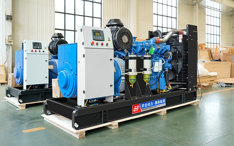
(3) Mantenimiento y conservación de generadores.
1. Mantenimiento de rodamientos de generador.
The two ends of the generator rotor are supported on the stator seat through rolling bearings.To maintain the accuracy of the bearings, lubrication requirements are marked next to the generator outlet box. Generalmente, after the generator has been running for 2000 horas, the lubricating grease should be replaced.When changing the oil, the bearing chamber and lubricating grease should be kept clean. Adding lubricating grease accounts for about 2/3 of the volume of the bearing chamber.It cannot be too much or too little, otherwise it will cause the bearing to overheat.
If the rolling bearings are severely worn or damaged, they should be replaced in a timely manner.The bearing and shaft sleeve have an interference fit, and the hot installation method can be used for disassembly and assembly by heating the shaft sleeve.
2. Inspección de la resistencia del aislamiento del generador y método de secado del generador.
When the generator is transported, stored, shut down for a long time, or affected by external humid environments, its insulation resistance should be checked.The insulation resistance of a generator is usually 200M Ω. If the insulation resistance is found to be too low, the generator should be dried to meet the insulation requirements before use.
The drying method for the generator is:
2.1 Short circuit current drying method: Short circuit the stator terminals of the generator in three phases, introduce some excitation current into the rotor, and after driving, the current in the stator coil should not exceed 50% of the rated current. After running for 3-4 horas, increase the stator current again, but not exceeding the rated current. The value should ensure that the temperature of the coil does not exceed the allowable temperature value (70 ℃ for thermometer method and 80 ℃ for resistance method).This method not only dries the stator, but also dries the rotor.
2.2 External heating drying method: Using an electric furnace, enclosed furnace, or steam pipe as a heat source, it can be placed around the generator and heated by natural convection with a blower, but the temperature of the hot air cannot exceed 90 ℃.To ensure uniform drying of the generator and prevent deformation of the shaft under prolonged heat, the blowing position or rotor should be constantly changed, and the surface temperature of the generator coil should be controlled not to exceed 85 ℃ (thermometer method).
2.3 Precautions for generator drying: Local overheating should be prevented during the heating process.During the drying process, the insulation resistance should be measured every half hour. After the value stabilizes for 3 horas, the drying is considered complete.The measured resistance should be greater than 0.5M Ω. It is not recommended to use coil heating method for excessively humid generators.
(4) Mantenimiento y conservación de la pantalla de control.
1. Precauciones de uso
Before using this control panel (cabinet), the operator must carefully read this manual and strictly follow the relevant regulations and requirements in the manual for installation, operación, y mantenimiento.
1.2 The components inside the control panel (cabinet) have been adjusted before leaving the factory, and users do not need to make any further adjustments.After the installation and external wiring of the control panel (cabinet) are completed and checked for errors, the front and rear doors should be locked. It is strictly prohibited to open them without operation during the working process.
Durante el funcionamiento de la unidad, the indication status of instruments (ammeter, voltmeter, frequency meter, power meter, etc.) should be regularly observed, and adjustments should be made at any time according to the prescribed requirements.Check the engine operation status through the LCD display screen, and promptly handle any abnormal working conditions to ensure the safe operation of the unit under normal conditions.
1.4 Regularly use the “self check” button to check if the alarm system is in normal working condition.
2. Requisitos de mantenimiento:
2.1 Keep the control panel (cabinet) clean and remove dust every six months.
2.2 Regularly check whether the circuit cables and connecting streets are corroded by oil and water, whether there is any looseness or detachment, and promptly deal with it.If there is any damage, it must be replaced promptly according to the prescribed specifications for foresight and cables.