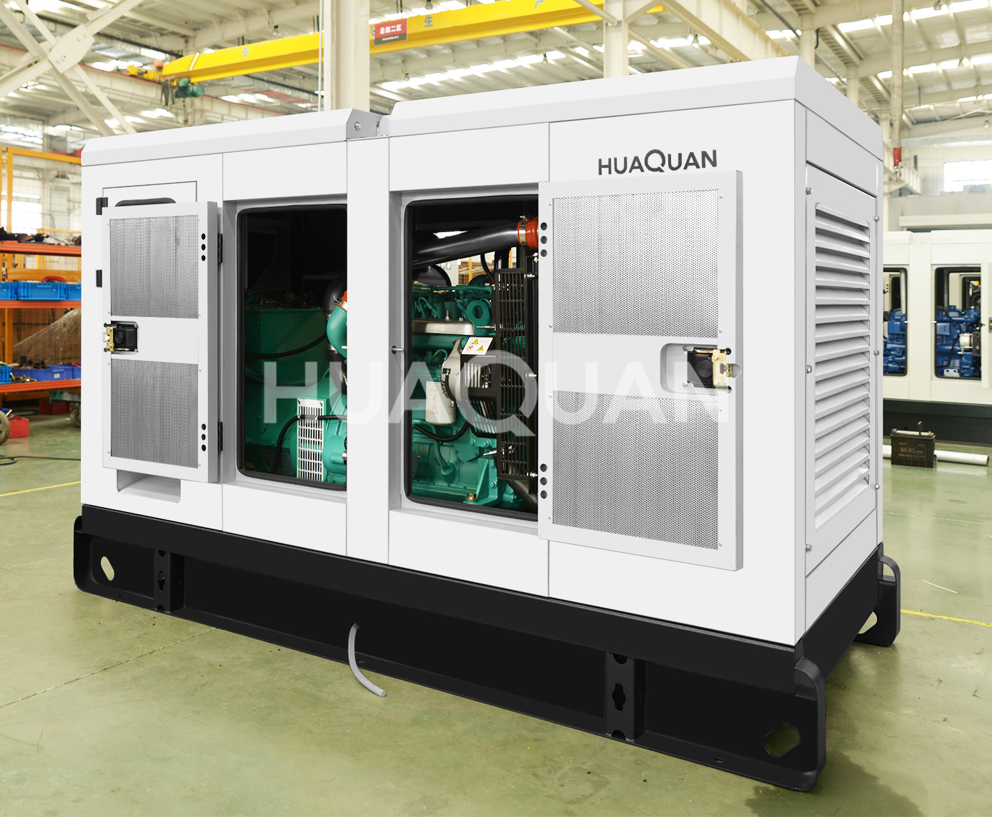
Sizing a Diesel Generator for a data center is one of the most critical and complex engineering calculations in power systems design. Unlike residential or commercial buildings where a 20% margin covers uncertainty, data centers require precise sizing that accounts for IT load characteristics, UPS charging, cooling starting surges, and N+1 redundancy requirements. An undersized generator means data loss; an oversized generator means wasted capital and wet stacking. Here’s the complete methodology.
Step 1: Determine the IT Load
Start with the actual IT power consumption — not the nameplate rating of servers. Modern servers typically operate at 40-70% of their nameplate power. Use power monitoring data (PUE measurements) from your existing infrastructure whenever possible.
| IT Load Metric | Typical Value | How to Measure |
|---|---|---|
| Server nameplate vs. actual | 40-70% of nameplate | Intelligent PDU monitoring |
| Power Usage Effectiveness (PUE) | 1.2-2.0 (industry average ~1.58) | Total facility power ÷ IT equipment power |
| IT load growth factor | 20-40% over 5 years | Business growth projections |
Step 2: Add the Cooling Load
Data center cooling typically consumes 30-50% of total facility power. The cooling system’s starting characteristics are the most challenging aspect of generator sizing.
Cooling System Starting Sequence
Data centers typically use one of three cooling approaches, each with different generator starting requirements:
| Cooling Type | Running Power | Starting Surge | Sequencing Strategy |
|---|---|---|---|
| Precision AC (CRAC/CRAH) | 15-25 kW per unit | 3-5× running (compressor start) | Stagger start — 10-15 sec between units |
| Chilled water system | 100-500 kW total | 5-8× chiller compressor | Chiller last — start pumps first, then chiller |
| Free cooling (economizer) | 5-15 kW (fans only) | 2-3× running | Minimal starting impact |
Step 3: Account for UPS Charging Surge
After a utility outage, the UPS batteries need recharging while simultaneously supporting the IT load. This charging current can add 10-25% to the UPS’s rated output — and it’s a highly distorted, non-linear load that Generators handle poorly.
UPS charging kW = IT load kW × 0.10 to 0.25 (depending on battery discharge depth and recharge time requirement)
Non-Linear Load Considerations
UPS input current has high total harmonic distortion (THD) — typically 15-30% for 6-pulse rectifiers and 5-10% for 12-pulse or active front-end (AFE) rectifiers. Generators are sensitive to non-linear loads because:
- Alternator voltage waveform distortion increases with THD
- AVR may hunt (oscillate) trying to regulate distorted voltage
- Excitation system may overheat from harmonic currents
- Generator must be oversized by 15-30% for high-THD loads
| UPS Rectifier Type | Input THD | Generator Oversizing Factor |
|---|---|---|
| 6-pulse SCR | 25-30% | 1.25-1.30× |
| 12-pulse SCR | 8-12% | 1.15-1.20× |
| Active Front End (AFE) | 3-5% | 1.05-1.10× |
| IGBT-based | <3% | 1.05× |
Step 4: Calculate Total Generator Load
Complete generator sizing formula for data centers:
Generator kW = (IT Load × Growth Factor + Cooling Load + UPS Charging Load) × Non-Linear Derating Factor × Safety Margin
Worked Example: 1 MW Data Center
| Component | Calculation | kW |
|---|---|---|
| IT load (current) | Measured from PDU | 600 kW |
| IT load growth (20%) | 600 × 1.20 | 720 kW |
| Cooling (PUE 1.5) | 720 × 0.50 | 360 kW |
| UPS charging | 720 × 0.15 | 108 kW |
| Subtotal | 1,188 kW | |
| AFE derating (1.10×) | 1,188 × 1.10 | 1,307 kW |
| Safety margin (1.10×) | 1,307 × 1.10 | 1,438 kW |
| Required generator | Next standard size | 1,500 kW |
Step 5: Redundancy Configuration
Data centers rarely rely on a single generator. The redundancy configuration directly affects the size and number of generators required:
| Configuration | Layout | Generators Required | Each Generator Size |
|---|---|---|---|
| N (no redundancy) | 1 generator | 1 | 100% of total load |
| N+1 | 2 generators, either can carry full load | 2 | 100% of total load each |
| 2N | Completely independent A+B paths | 4 (2 per path) | 100% per path |
| 2(N+1) | Maximum redundancy | 4+ (2+ per path) | 100% per path |
Critical Data Center Generator Requirements
- NFPA 110 Level 1 compliance: 10-second start-to-load capability
- 96-hour on-site fuel storage minimum (many facilities store 7-14 days)
- Load bank test connections: Permanent or portable load bank testing at 75-100% rated load annually
- Bypass isolation: Generator must be serviceable without disrupting power to the data center
- Black start capability: Generator must start with no external power (battery-only cranking)
- Fuel polishing: Automated fuel filtration system to maintain diesel quality
Huaquan Tip: Data center generator sizing requires specialized expertise. Huaquan Power provides free load analysis and sizing calculations for data center applications from 200 kW to 10 MW, including redundancy configuration consulting and fuel system design.
⚡ Explore Related Solutions
- 🏭 500kW Diesel Generator
- 🏭 1000kW Diesel Generator
- 🏭 500kW YC Diesel Generator
- 🔧 KMS (Cummins/Doosan) Series
- 🏥 Data Center Generator Solutions
- 📋 Diesel Generator Sets
- 📋 Order Process — How to Buy
- 📋 Contact Us
💡 Need a customized solution? Contact our engineering team for project-specific recommendations.