< img height="1" width="1" style="display:none" src="https://www.facebook.com/tr?id=818233107660385&ev=PageView&noscript=1" />
x
Send Your Inquiry Today
Quick Quote

Power Factor Correction for Generators.

Power factor correction is one of the most impactful yet overlooked strategies for reducing generator operating costs and improving system performance. A facility operating at 0.7 power factor wastes 30% of the generator’s capacity on reactive power that does no useful work. Correcting to 0.95 can reduce generator size requirements by 25%, lower cable costs, and decrease fuel consumption 2-5%. This guide covers the theory, methods, and practical implementation of power factor correction for generator systems.

Understanding Power Factor

Power factor (PF) is the ratio of real power (kW) to apparent power (kVA). It measures how effectively electrical power is being converted into useful work. A PF of 1.0 means all power does useful work; a PF of 0.7 means 30% of the current is reactive, flowing back and forth without producing work.

Load TypeTypical PFReactive PowerImpact on Generator
Resistive (heaters, incandescent)1.0NoneNo reactive burden
Inductive (motors at full load)0.85-0.90LowModerate reactive burden
Inductive (motors at half load)0.60-0.75HighSignificant reactive burden
Transformers (unloaded)0.20-0.40Very highSevere reactive burden
UPS with 6-pulse rectifier0.65-0.75High + harmonicsWorst case for Generators
LED lighting with drivers0.5-0.9VariesHarmonic content is key factor

Why Low Power Factor Costs Money

Low power factor increases costs in three ways:

  • Larger generator required: A 400kW load at PF 0.7 needs 571kVA vs. 421kVA at PF 0.95—a 36% larger generator. The cost difference for a 500kVA vs. 630kVA unit is typically $8,000-15,000.
  • Higher cable and switchgear costs: Cables carry current proportional to kVA, not kW. At PF 0.7, you need 36% more current capacity in all distribution equipment.
  • Increased fuel consumption: Higher current causes more I-squared-R losses in the alternator and cables, adding 2-5% to fuel consumption at PF 0.7 vs. 0.9.

Methods of Power Factor Correction

1. Capacitor Banks — The most common and cost-effective method. Capacitors supply the reactive power that inductive loads would otherwise draw from the generator. Fixed capacitor banks are installed at the main distribution panel; automatic capacitor banks switch capacitors in and out based on real-time PF measurement.

2. Synchronous Condensers — A synchronous motor running without mechanical load can generate or absorb reactive power by adjusting its excitation. More common in large industrial plants (>5MW). Expensive but very reliable and controllable.

3. Active Power Factor Correction (PFC) — Electronic circuits that shape the input current waveform to match the voltage waveform. Standard in modern UPS systems, VFDs, and high-quality LED drivers. More expensive than capacitors but also corrects harmonic distortion.

Sizing Capacitor Banks for Generators

The capacitor bank size depends on the existing PF and the target PF: kVAR needed = kW x (tan(arccos(PF_existing)) – tan(arccos(PF_target))). For a 400kW load improving from PF 0.7 to 0.95: kVAR = 400 x (1.02 – 0.33) = 276 kVAR. Round to 280 kVAR (standard size).

Existing PFTarget PFkVAR per 100kW LoadGenerator Size Reduction
0.700.9569 kVAR36%
0.750.9555 kVAR27%
0.800.9542 kVAR19%
0.850.9530 kVAR12%
0.900.9517 kVAR6%

Critical Warning: Leading Power Factor

Over-correction (PF > 1.0, leading) is dangerous for generators. Leading PF causes the alternator voltage to rise uncontrollably, damaging the AVR, insulation, and connected equipment. Never over-correct. Always target PF 0.95 lagging, not 1.0. Switch capacitors off when their associated motors are off to prevent leading PF during low-load periods.

FAQ

What power factor should I target?

Target PF 0.95 lagging. This provides near-optimal efficiency with a safety margin against leading PF. Do not target PF 1.0 because load variations can push the PF leading, which damages generator voltage regulation. Some utilities require PF 0.90 minimum and penalize below that.

Can I use the same capacitors for utility and generator power?

Yes, but with caution. Capacitor banks sized for utility power may over-correct when running on a generator (because the generator has different impedance characteristics). Use automatic capacitor banks with PF controllers that maintain the target PF regardless of power source.

How do harmonics affect power factor correction?

Harmonics from non-linear loads (UPS, VFD, LED drivers) interact with capacitors and can cause resonance, amplifying harmonic voltages to damaging levels. Always install detuning reactors (5-7% inductance) in series with capacitors when harmonic-producing loads exceed 20% of total load.

Does power factor correction reduce my electricity bill?

If your utility charges for kVA demand or penalizes low PF, correction provides direct savings. Even without utility penalties, PF correction reduces I-squared-R losses in your distribution system, typically saving 2-4% of total energy costs. The payback period for capacitor banks is usually 12-18 months.

What is the difference between displacement PF and true PF?

Displacement PF measures the phase angle between fundamental voltage and current. True PF includes the effect of harmonics: True PF = Displacement PF x 1/sqrt(1 + THD-squared). For generator sizing, true PF is what matters because the alternator must carry the total current including harmonics.

Can a generator handle capacitive loads?

Generators are designed for lagging (inductive) PF loads. Moderate capacitive loads (PF 0.95 leading) are acceptable, but significant capacitive loading causes overvoltage and AVR instability. If your facility has large capacitor banks, ensure they are switched off when their associated inductive loads are off.

How do I measure power factor on my generator?

Use a power quality analyzer at the generator output terminals. Measure over at least 24 hours to capture load variations. The generator controller may also display PF. For facilities with both linear and non-linear loads, ensure the analyzer measures true PF (including harmonics), not just displacement PF.

What is detuning and why is it needed?

Detuning adds inductance (5-7%) in series with correction capacitors to shift the resonant frequency below the lowest harmonic frequency (typically below 200 Hz for 50Hz systems). This prevents resonance between capacitors and the generator’s inductance, which could amplify harmonic voltages to destructive levels.

How much does power factor correction cost?

Capacitor banks typically cost $15-25 per kVAR for fixed banks and $25-40 per kVAR for automatic banks. For a 400kW facility improving from PF 0.75 to 0.95, the 220 kVAR bank costs approximately $4,400-5,500 (fixed) or $6,600-8,800 (automatic). Payback is typically 12-18 months through reduced demand charges and fuel savings.

Should I install capacitors at the load or at the main panel?

Installing capacitors at the load (motor) is most efficient because it reduces current in the cables between the panel and the motor. However, it is more expensive (multiple small units vs. one large unit). For generator applications, install automatic capacitors at the main panel so they can be controlled as a group and prevented from causing leading PF on the generator.

Technical Deep Dive: Reactive Power and Generator Interaction

Understanding how reactive power interacts with the generator is essential for proper power factor correction. Unlike the utility grid (which has massive rotational inertia and essentially infinite short-circuit capacity), a generator has limited capability to absorb or supply reactive power. This fundamental difference affects every aspect of power factor correction design for generator-supplied facilities.

Generator AVR Response to Reactive Loads

The automatic voltage regulator (AVR) maintains output voltage by controlling the excitation current in the alternator rotor. When inductive loads draw reactive power, the voltage tends to sag, and the AVR increases excitation to compensate. This increased excitation current heats the rotor winding, which is often the limiting factor for continuous reactive power delivery. At PF 0.7, the alternator must supply 43% more current than at PF 1.0 for the same kW output, and the rotor excitation current increases by 30-50%.

When capacitive loads push the PF leading, the AVR faces the opposite problem: voltage tends to rise, and the AVR must reduce excitation. However, the AVR has a minimum excitation limit below which it cannot maintain control. If the leading reactive power exceeds this limit, the voltage rises uncontrollably—a condition called self-excitation that can damage the alternator and connected equipment within seconds.

Harmonic Interaction with Capacitors

Non-linear loads (UPS systems, VFDs, LED drivers, computer power supplies) produce harmonic currents that interact with the generator’s inductance and any correction capacitors. The interaction creates parallel resonance at specific harmonic frequencies, which can amplify harmonic voltages to 5-20x their normal level. This is why installing capacitors without detuning reactors is dangerous in facilities with significant non-linear loads.

Harmonic OrderFrequency (50Hz system)Typical SourceAmplification Risk
3rd150 HzSingle-phase rectifiersHigh (zero-sequence)
5th250 Hz6-pulse rectifiers (UPS)Very High (most common resonance)
7th350 Hz6-pulse rectifiersHigh
11th550 Hz12-pulse rectifiersModerate
13th650 Hz12-pulse rectifiersModerate

The 5th harmonic is the most problematic because it is the dominant harmonic from 6-pulse rectifiers (used in most UPS systems) and coincides with the natural resonance frequency of many generator-capacitor combinations. A 5% detuning reactor shifts the resonance below 250 Hz, preventing 5th harmonic amplification.

Industry-Specific Power Factor Challenges

Data Centers: The Double Penalty

Data centers face a double power factor penalty: UPS systems have low displacement PF (0.8-0.9) AND high harmonic content (10-30% THDi). The combined true PF can be as low as 0.6-0.7. This means a data center with 800kW of IT load may require a 1140-1330 kVA generator instead of 840-1000 kVA at PF 0.95. The cost of oversizing: $15,000-40,000 per generator, plus proportionally larger switchgear and cables.

Manufacturing: Motor-Heavy Loads

Manufacturing facilities with large motor populations (pumps, fans, compressors, conveyors) often operate at PF 0.7-0.8. The individual motors may have acceptable PF at full load (0.85-0.90) but drop to 0.5-0.6 at partial load. Since most motors run at 50-75% of their rated load, the aggregate facility PF is typically poor. Installing capacitors at each motor (at-load correction) is the most efficient approach but more expensive than a single bank at the main panel.

Commercial Buildings: LED Lighting Transition

The transition from fluorescent to LED lighting has introduced a new power factor challenge. Older fluorescent lighting with magnetic ballasts had PF 0.5-0.6 (inductive, easily corrected with capacitors). Modern LED drivers have PF 0.5-0.9 depending on quality, and the low-quality drivers produce significant harmonic distortion (THDi 20-40%). When correcting PF for LED loads, detuning reactors are mandatory.

ROI Calculation: Power Factor Correction

ScenarioBefore CorrectionAfter CorrectionAnnual Savings
400kW at PF 0.7, standby 500h/yr571 kVA generator needed421 kVA needed (PF 0.95)$8,000 generator savings + $1,600 fuel/yr
400kW at PF 0.7, prime 4000h/yr571 kVA generator needed421 kVA needed$8,000 generator savings + $12,800 fuel/yr
800kW at PF 0.75, data center1067 kVA needed842 kVA needed$22,000 generator savings + $19,200 fuel/yr
200kW at PF 0.8, manufacturing250 kVA needed211 kVA needed$4,000 generator savings + $3,200 fuel/yr

Additional FAQ

How do I size a capacitor bank for a generator-powered facility?

Measure your facility’s actual power factor over 24-48 hours using a power quality analyzer. Calculate the required kVAR: kVAR = kW x (tan(arccos(PF_current)) – tan(arccos(PF_target))). Add 10% safety margin and round up to the nearest standard size. Always install detuning reactors if non-linear loads exceed 20% of total load. For automatic banks, size each step to be no larger than 25% of the total kVAR to maintain smooth regulation.

What happens if my power factor correction causes leading PF on the generator?

Leading PF is dangerous for generators. Symptoms include: rising output voltage that the AVR cannot control, flashing exciter diodes, and potential damage to connected equipment from overvoltage. If you observe rising voltage with decreasing load, immediately disconnect some capacitor steps. Install a PF relay that trips capacitor steps when PF goes leading.

Can I use active harmonic filters instead of capacitors?

Yes. Active harmonic filters (AHF) correct both displacement PF and harmonic distortion simultaneously, with no risk of resonance. They are more expensive ($80-150/kVAR vs. $15-40/kVAR for capacitor banks) but provide superior performance in facilities with high harmonic content. AHF is the recommended solution for data centers and facilities with more than 30% non-linear loads.

What is the 3/3 pitch alternator and how does it help?

A 3/3 pitch alternator has a winding configuration that naturally suppresses third harmonic currents, reducing the need for derating when powering non-linear loads. Standard 2/3 pitch alternators are more common but require 20-30% derating for non-linear loads above 25%. When specifying generators for UPS-heavy applications, request 3/3 pitch alternators to avoid oversizing.

How does power factor affect generator parallel operation?

In paralleled generators, reactive power sharing is controlled by the AVR’s voltage droop setting. If one generator has different PF than another (due to uneven load distribution), the AVRs fight each other, causing circulating currents between the generators. Proper reactive power sharing requires matched AVR settings and cross-current compensation (CCC) or reactive differential (Droop) compensation on all paralleled units.

Huaquan Real-World Projects

At Huaquan Power, we’ve deployed generator systems across diverse applications worldwide. Here are some representative projects:

CountryPower RatingApplicationProject Highlights
Overseas450kWPower StationHuaquan delivered a 450kW diesel generator system for power station applications in Overseas, featuring customized configuration for local conditions with reliable after-sales support.
Vietnam600kWPower StationHuaquan delivered a 600kW diesel generator system for power station applications in Vietnam, featuring customized configuration for local conditions with reliable after-sales support.
New Zealand550kWHospitalHuaquan delivered a 550kW diesel generator system for hospital applications in New Zealand, featuring customized configuration for local conditions with reliable after-sales support.

These real-world deployments demonstrate our engineering team’s capability to deliver reliable power solutions tailored to specific application requirements and environmental conditions. View all overseas case studies →

Recommended Generator for Your Application

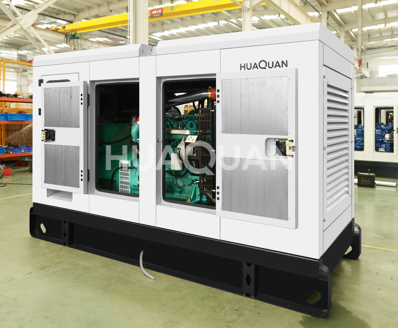
100-500kW Diesel Generator

100-500kW Diesel Generator

Medium-duty diesel generator for industrial and commercial applications.

Key Features:

  • ISO 8528 compliant
  • Customized voltage & frequency
  • Remote monitoring available
  • Global shipping & on-site installation

View Specifications & Get Quote →

Related Resources