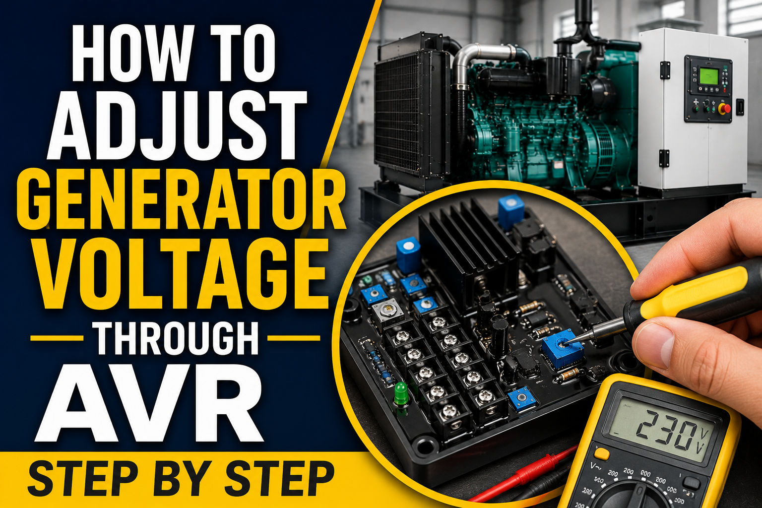
Correct Generator Voltage is vital to the reliable operation of your facility’s electrical equipment. When a generator’s output voltage falls below its rated voltage, heavy electric motors will overheat and stall. If it generates a voltage that’s too high, it would destroy sensitive microprocessors and lighting systems almost immediately. You might notice symptoms like flickering lights, unstable power output or UPS systems that keep shutting down over and over.
The AVR, or Automatic Voltage Regulator, controls this power. It may seem like a simple adjustment, but it’s a delicate process with the AVR. According to the manufacturer’s documentation, the voltage, stability, frequency protection and excitation current controls are isolated and extremely sensitive and are common features in AVR models. Each model is different, and each generator and AVR will function and adjust differently, so always check the manuals for that generator and AVR. You can only adjust the AVR once you fully verify engine speed, frequency, loading and physical wiring.
In this article by Huaquan, you will learn how to safely adjust your generator’s output voltage through the AVR, correctly identify the adjustment trimmers, and properly test the system under load to ensure stable power.
What Is Generator Voltage?
Rated voltage versus measured voltage
The voltage your generator is designed to produce is called the rated voltage; it is usually given as 120V, 230V, 240V, 400V, or 480V. This voltage is correct for the generator and based on each region’s electrical requirements, as well as the model of generator you are using and its internal phase configuration. If you are Troubleshooting, it’s important to know the difference between line-to-line measurements (across two hot phases) and line-to-neutral measurements (from one hot phase to the neutral return).
How generator voltage is produced
The generation of voltage is a process that is analogous to a chain reaction:
- The prime mover (diesel or gas engine) drives the alternator.
- The spinning rotor generates a magnetic field.
- As this magnetic field passes through the stationary stator windings, an electrical output results.
- How powerful that magnetic field gets is the excitation strength, which directly controls the final output voltage.
Why generator voltage changes
Not all the time is the AVR the culprit if the voltage deviates from the target. Common causes include:
- Incorrect engine speed: If the engine can not spin up to the speed that is set, then voltage will of course decrease.
- Sudden or excessive load: When huge motors start, they draw down the voltage for a short time.
- AVR calibration: Over time, the regulator has drifted from the factory calibration.
- Loose sensing connections: If the wires move around, the AVR will not be able to accurately measure the output.
- Damaged excitation components: Bad diodes or worn brushes reduce the magnetic field.
- Alternator winding faults: Internal copper shorts reduce the machine’s ability to produce power.
What Does the AVR Do in a Generator?
How an automatic voltage regulator works
The AVR is the alternator’s “brain.” It continually checks the generator’s output voltage, also known as sensing voltage. It then compares the measured voltage with a hard-coded reference voltage value. When the voltage is too low, the AVR immediately increases the magnetic field by increasing the excitation current to the rotor. Mecc Alte says this is like a closed-loop process where the system measures the output, compares it to a reference signal, and then actively controls it.
Common controls found on an AVR
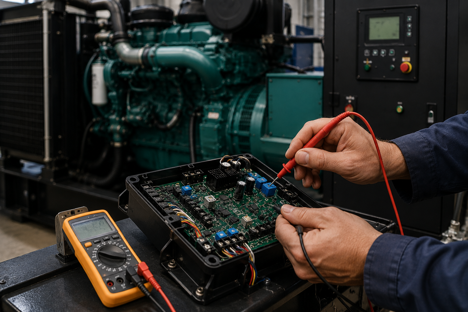
Depending on the model, these small adjustment screws, also known as trimmers, sit on the AVR board.
- VOLT: Changes the desired output voltage up or down.
- STAB: Regulates voltage stability, response time and acts against hunting (rapid oscillation).
- Hz or UFRO: Underfrequency protection (low engine speed, reduces voltage).
- AMP: Restricts maximum excitation current to avoid overheating.
- Remote voltage potentiometer: Separate dial, fitted on control panel.
Why the VOLT control should not be confused with STAB
Turning the VOLT screw adjusts the actual target voltage. Turning the STAB screw changes how quickly or smoothly the AVR reacts to load changes. If not set properly, the stability trimmer can result in serious voltage oscillation and thus render the generator completely useless.
When Should Generator Voltage Be Adjusted?
All of the following must apply:
- The voltage is always held slightly higher or lower than the rated value and is stable and smooth.
- Check that the frequency (Hz) and the speed of the engine (RPM) are ideal.
- The output is not very volatile.
- The wiring arrangement is exactly as specified on the nameplate.
- There is no overload of the generator at the present time.
- The manufacturer’s manual clearly permits adjustment in the field.
When AVR Adjustment Will Not Fix the Problem
Never use a screwdriver to adjust the AVR when:
- Frequency too low: AVR is taking action to prevent damage to the alternator.
- Instability of the engine speed: If the engine has a tendency of surging RPMs, then its voltage will always surge.
- The first heavy load to start causes the voltage to drop: NOT a calibration problem.
- The difference between phases is much lower than the other phases: This means that there is a fault in the stator winding.
- Output changes at random: Suggests a line is not tightly connected or that a component is not working.
- Sensing wires on AVR are loose or visibly damaged.
- The voltage selector switch or terminal links are set wrong.
Adjusting the Generator Voltage Using AVR: Step by Step
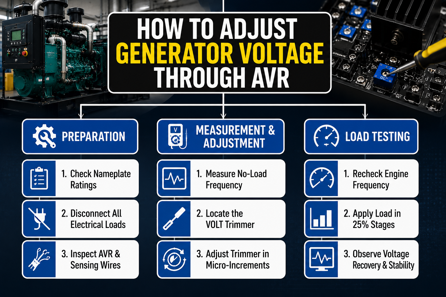
Step 1: Check the Generator Nameplate
First, check the metal nameplate that’s riveted to the alternator. Enter the rated voltage, rated frequency, rated speed (RPM), single-phase or three-phase, and maximum current and the wiring configuration.
Step 2: Disconnect Electrical Loads
Turn off any powered equipment or open the main power output breaker. This needs to start with a voltage test with no load.
Step 3: Inspect the Generator Before Starting
Turn the power off completely and inspect for loose main terminals, damaged AVR wires, burned plastic connectors, moisture, corrosion, broken thin sensing leads and any visible physical damage to the AVR PC board.
Step 4: Start the Generator and Allow It to Stabilize
Start the engine and warm the engine up for a few minutes. Keep an ear on the engine and watch for engine noises like chugging, misfiring or uneven speed. Verify that the RPM remains absolutely constant under the mechanical or electronic governor.
Step 5: Measure Frequency Before Adjusting Voltage
While connected at the main terminals with no load connected, measure the output frequency (Hz). Compare with the rated value of the generator (50Hz/60Hz). Adjust the AVR setting after correcting any engine-speed issues. Cummins’ troubleshooting procedures tell the technician to check engine voltage with no load and then apply load to the engine when checking the voltage, to determine if there is an electrical problem or an engine problem.
Step 6: Measure the Existing Generator Voltage
The following section covers how to use your True-RMS multimeter:
- If the equipment is single-phase: Measure line to neutral and line to line (where applicable), e.g., 120V/240V split-phase.
- If it is a three-phase piece of equipment, then: Measure all three line-to-line combinations (L1-L2, L2-L3, L1-L3) and measure each line to neutral. Record any significant phase imbalance.
Step 7: Locate the AVR and Identify the VOLT Trimmer
Go to the AVR, using your service manual. Verify the particular adjustment screw has a VOLT or V, or V-ADJ marking or equivalent to a model. Please be sure not to change STAB, Hz, UFRO or AMP parameters by accident. Prior to touching the trimmer, take a picture or mark with a marker the original trimmer position.
Step 8: Adjust the VOLT Control Gradually
With an insulated adjustment tool, make small adjustments, only a tiny fraction of a millimeter at a time. Always do it according to the direction of rotation in the AVR manual (don’t assume that it’s clockwise that puts more voltage on all models). Wait after each micro adjustment to allow the electrical output to settle. Check your external voltmeter all the time.
Step 9: Set the Voltage to the Manufacturer’s Specification
Adjust the voltage to the nameplate value. Don’t take a shot at it. Account for whether the value you are given is line-to-line or line-to-neutral. Don’t make that mistake by intentionally dropping the no-load voltage to make up for it when it is a heavy load; this will burn out equipment when the load turns off again.
Step 10: Recheck Frequency
Be sure the frequency (Hz) is not lower when adjusting the voltage. Ensure the engine is operating properly. If the voltage and frequency change significantly together, then it’s a governor or engine horsepower issue, and NOT the AVR issue.
Step 11: Apply the Load Gradually
Start to apply the electrical load gradually. Typical test stages are 25%, 50%, 75% and full rated load (load bank if applicable). Record the voltage, frequency, current (amps) and stability measurements at each stage.
Step 12: Observe Voltage Recovery
Watch the multimeter as you apply a heavy load. Test to see if the voltage:
- Recovers efficiently and quickly in a few seconds.
- Drops excessively and stays low.
- Overshoots dangerously high.
- Alternates up and down repeatedly (oscillates or hunts up and down).
- Remains wildly different between phases.
Step 13: Adjust Stability Only When Necessary
STAB adjustment is not a part of regular voltage calibration. Do not use unless the voltage is oscillating under load and also only when the manufacturer has a specific tuning procedure. Always mark the original setting first, and never make major changes.
Step 14: Complete the Final Inspection
Turn off the generator. Tighten up all panels and put covers back on. Clear the generator cabinet of all tools. Turn the unit back on, take final voltage and frequency readings and enter the date and load applied for the test in the maintenance log book.
Conclusion
Correcting a generator’s voltage is a very important maintenance procedure, and it relies on much more than just twisting the VOLT trimmer on a circuit board. The key elements to a healthy electrical output are all of these: perfect engine speed, clean fuel delivery, good wiring connections and a mechanically good alternator. Before making any adjustments on the AVR, make sure that the frequency is correct, check the load demand, check the sensing wires and rule out any problems with the engine governor. If this voltage is low, unbalanced or not stable after a simple calibration, it’s time to go back.
Have trouble getting the generator voltage steady or correct? Don’t wait for unstable power to wreak havoc on your facility’s connected equipment; have a trained technician service the AVR, excitation system and windings of the engine’s alternator. Contact the Huaquan team today for professional AVR calibration, advanced load-bank testing, and expert generator repair services to protect your facility’s critical electrical equipment.